Monday, September 30, 2013

Rocky & Bullwinkle: converting the Lion hat trick to 32 volts

I can solder!  WOOT!
I dropped some coin on some basic electronic hobbyist tools, read some guides, watched some youtube, and had a very specific plan of action to abide by.

For the longest time the LION hat trick plastic was unobtanium.  Each Rocky & Bullwinkle needed a new one, and up until recently there were no reproductions.  And those reproductions are probably already sold out!  (I got mine and replaced that a while back)

The reason they were so rare?  The lion was wired to 50 volts, while the other 2 were given 32 volts.  This is by design, maybe to make the lion seem scarier?
Stitched from a somewhat fuzzy scan going around.  Click to embiggen.

First thing I did was clean the assemblage a bit.  I didn't bother taking it apart, but even so I could get some grime away from the pivot points and clean up the upper left guide wires.

And here is my handy-work!

It wasn't a fabulous job, but it WORKS!  The wires are secure, I ran through the coil test, and we're allllll good.
The yellow/purple wire you see at the left is the 50V power wire.  I bought some heat-shrinking wire tubing and a little torch, but failed a bit in putting butane in said torch, so I will do a better job closing off that wire later.  For now, the electrical tape should suffice.

A selection of my soldering gear:
Starting in the upper left, going clockwise:  wire stripped, flux paste, 16 gauge wire, brass tip cleaner, desoldering braid, 60/40 0.05mm solder, 25W Weller iron, solder pump.


New list format....

STUFF TO DO
diagnose fix power board issues / replace/resolder capacitors
adjust flippers to the dots
try troubleshooting audio connections: excessive hum + hum sound oscillating with light show
replacing the SAVED decals.
find a replacement WABAC ramp.
get/install a Boris button
level the legs
deep disassemble-everything clean

DONE
wire Lion to 32 V instead of 50 V
replace the back box hat trick padding
Replace plastic Lion in hat trick
replace ball drain kicker
Update ROMs to 1.3
remove pop bumper screw.
repair first left orbit (hat trick) switch so that the diverter can work
CLEAN ALL THE THINGS.
replace beer seal


At this point, the only major thing left will be the power board capacitors.  Once I get that issue resolved, the game will be playing 100% and everything else is really just small aesthetic stuff.

Thursday, September 26, 2013

SF2: new issues to tackle

I am waiting for my parts to arrive, so in the meantime, let's investigate other issues.
With the ground kind of wonky, the system made a big BooooOOOOOmmmm wow sound when you turned it on, and then had a loud hum.  At the bottom of the cab I disconnected the woofer and now it's much nicer to work on and turn off and on.


I got the driver board in, I put it on to tournament mode free play, and got a few days of good gameplay and analysis before I noticed something new:  
The right slingshot solenoid was always engaged.  Well, actually not always, but always engaged when the flippers were active.

The Q relay (upper right in schematic) is in the cabinet and controls the activity on the playfield.
It is normally off, and when engaged it allows the pop bumper, slingshots, and main flippers to be active.
When the Q relay is not engaged, the solenoid for the slingshot ("Right kicking rubber") is no longer on.


The connector in the upper left, above, is labeled A3J5 and comes in from the lightbox, the driver board.
Solenoid 2 is controller via Q3, R64, C14, and D3.


The first thing I was curious about was if the switches on the playfield were jammed on or had wiring issues.  I used my DMM and confirmed full resistance across the nodes, and zero resistance when I pressed the switch, so they were operating nominally.
Here they are represented in the switch matrix:
click to embiggen
The adjoining switches in the matrix also all work, so it's not a switch problem.
I wonder if there could be a spontaneous failure of a transistor on the driver board?
In the meantime I can remove Fuse 17 and just play without the slingshot kicker.

yeah I should go learn how to measure across these properly.


Another piece of the puzzle: 
When I go in to test mode, I get the main test mode screen saying "TEST MODE:  USE L FLIPPER TO CHANGE / R FLIPPER SELECT" but then NOTHING happens.  Left, right flippers, and start button, all do nothing there.  WEIRD.
I noticed this issue at the same time since the first step to look in to the solenoid issue was to check the solenoid and switch tests.


EDIT:  removed fuse 17, disabling the right kicker, and now the test mode works again.
Also:  the switches on the slingshot are fine, the lights still turn on when hit.  This does lead me back to the  driver board components, as the switches are shared for the lights and the solenoid, and those are fine, and at the back end of the circuit the Q is doing it's job fine, so it has to be somewhere after the switch matrix and before the solenoid.

Sunday, September 22, 2013

Street Fighter 2: documenting the issues

I'm going to move to a different format for lists.  Numbers won't cut it for this game.  It's a player's game.  It's been operated on, heavily.
There will be much damage to undo, and much healing to take place.
I will just put together a laundry list of things, sorting it from MOST IMPORTANT at top.
Then, I will put together a list of things DONE, just in the order I do them.

TODO
new Gottlieb System 3 power module + fuses
reattaching all of the ground wires
replace VUK solenoid to correct one (should be A-26450)
fix the ramp subways / Stargate ramps  (replacing fuse?)
deep clean of playfield, removing all plastics and cleaning the screws
replace left flipper solenoid with correct one  (should be A-25959)
cleaning the under-playfield troughs
firmly attaching the coin doorreplace playfield glass
replace all playfield rubbers
get cliffy protectors replace 3 Gottlieb flipper bats
Replace car crash flipper rubber

DONE
new beer seal
Flipper rubber for Chun Li
Replaced flipper rubbers (except car crash flipper)
Cleaned backbox charring + replaced dead + charred lightbulbs
initial basic playfield cleaning


This is a weird thing to have:  extended padding at the top of the VUK cover.  Reason?  The ball usually jumps out and BANGS the glass!  Reason?  I found there was a Williams coil in there, AE-24-900, when it should be a Gottlieb A-26450.  New part ordered.  And the playfield glass does need replacing, but not going to bother until this is under control.


This is the right VUK, and it works dandy.

This shows how a lot of the metal parts are going to need some love.


Here we can see the left and right ramps, and I call them Subways but they call them Stargate Ramps.  They are supposed to raise up, giving an extra shot, but neither do.  This seems suspicious!  I checked the schematics and found F25 is a fuse for BOTH, so time to order a replacement fuse.
Hopefully that will do the trick.

Thankfully, the software compensates in the mean time, accepting a successful shot up either ramp when really it is supposed to be open underneath.


Oh did I mention the coin door is basically held on by bubble gum?
ummmm nope.

Yeah...  let's get that taken care of.


F25 (bottom, 2nd from left) looks suspiciously different.


Add this to the list of weird power issues:  There is no LINE INPUT FUSE.  the whole thing looks melted.  PBResource has these entire units on special for $25 so I am just going to try and play it safe and get a replcement.  Oh and that ground wire in the upper right was NOT initially connected.
That fuse F1 is just before the "Line Filter", so who knows if and how that has potentially mucked things up, with the line filter being unprotected.
Once I get this replaced I will begin addressing the grounding issues, as well get in to the known Gottlieb System 3 grounding problems.


I am not sure if it is at all related, but I noticed some sparks/arcing by the right flipper.  the shooter lane assembly here is transparent, allowing you to faintly see through.


You can see the sparks in this short video:

Saturday, September 21, 2013

success!


Success!   Street Fighter 2 is up, running, and lots of fun.

I got a replacement board, took mine out, put the new one in, and oh man it works!
There is SO MUCH to do on this machine, so expect a rambling itinerary in the future.

In the meantime, let's take a final look at the board damage, and a bit of the replacement process.


one last look at the damage
 
The PCB boards were held on by 5 of these plastic nubs.  I found the best way to remove them was to work aroudn the edges with a flat headed screwdriver.
My damaged board, ready to be shipped to Someone Who Knows What They Are Doing.

Wednesday, September 18, 2013

Royal Flush: simplifying the schematics

NOTE:  I don't even have Royal Flush any more, but I realized I had this in my drafts folder from 4 months ago and never posted it.  I liked what I did, so thought best to put it up for future Royal Flush owners.

I posted the full schematics 2 posts back, but I'm working on the startup.  Let's simplify things.
I've taken the schematics and edited it down to just the relays used in startup.
GONE:  All lights, transformer, scoring, chimes, flippers, replay, etc.
ADDED: all useful relay labels

CLICK TO EMBIGGEN!

I also received the suggestion to work to isolate the problem, so I disconnected the coin door, the back box, and the playfield.  Same issue continues: the motor still runs.
but at the very least, we know the issue is now down in the box.

Rocky & Bullwinkle hat trick switch

One thing I'm learning here is to apply your newly gained/practiced knowledge against your earlier issues whenever possible.

I went back to Rocky & Bullwinkle, where the hat trick diverter has never worked since I got it.  The switch wasn't responding, which means shooting the hat trick doesn't dunk the ball in to the VUK hole.

After spending a lot of time with wiring diagrams, I decided to pull out the R&B schematics and verified the switch matrix wire colours that correspond to the first left orbit switch.
I pulled up the playfield and found them and the connector that put them in to the loop.  It is important to note that a whole bank of switches wasn't disabled, so the receiving connector is fine, they are passing their signal along it's merry way to the other switches in line.

the connector, disconnected.
The bottom wires run up to the switch on the playfield.  I couldn't tell how secure and snug of a connection they were making, especially since I see the plastic wire coating on the terminating end.
I got out my dental pick (really, the most functional tool for pinball repair ever) and jammed the wires deeper in to the connector. 
I also took a small piece of electrical tape, cut the width in half, and used that as a ribbon to secure that sub-connector to the wired connector.  Plugged it back in to the chain, booted it up and LO! The Hat Trick worked!
The diverter is lightning fast, captures the ball in the VUK, and I am treated to the PROPER Hat Trick animation.  Ball is then fed, oh so conveniently, to the left flipped.

Suddenly, the game becomes MUCH easier.  :)

So... I guess I'm on fire tonight with the whole "figuring things out" groove.  Another problem solved.


Strike off #10, and let's updates #13 and #5 to be more specific...
1) replacing the SAVED decals.
2) wire Lion to 32 V instead of 50 V
3) replace the back box hat trick padding
4) replace plastic Lion in hat trick
5) try troubleshooting audio connections: excessive hum + hum sound oscillating with light show
6) replace ball drain kicker
7) find a replacement WABAC ramp.
8) Update ROMs to 1.3
9) remove pop bumper screw.
10) repair first left orbit switch so that the diverter can work and the back glass animation can be awesome once more.
11) level the legs
12) CLEAN ALL THE THINGS.
13) diagnose fix power board issues / replace/resolder capacitors
14) replace beer seal
 15) adjust flippers to the dots

Street Fighter 2: connector anxiety

So my friend sent me a new Gottlieb system 3 driver board and while I await it's arrival I wanted to make sure all of the connectors are correct.

The connectors come labeled, but the glue is long since hardened and many of them have followed off.  Those that still had a sticker hanging on for dear life, I bent in to the machines mouth with sharpie in hand and attempted scribing the connector names on them.  Not as easy as it sounds from my awkward angles of approach!

I unplugged the 2 mismatched connectors.  There was a pair still labeled, so that was an easy connection, and that left just 2 cables unplugged:
this one from the transformed

this one (oh so elegantly labeled) heads up to the back box


Then I got nervous.  See ANY ISSUES HERE?
Yeah, top cables has 18 wires going in, bottom one has 14 wires coming out.  Was this expected?  WTF?  WHYYYYY?


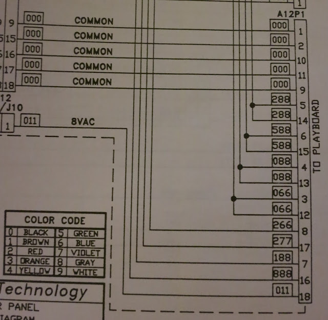
I dug in to the schematics:

A12J1 connector

A12P1 connector

As we can see it was indeed by design.  For REASONS.
but my doubt was squashed, connected them, and I should be done with those dastardly under-playfield connectors now.

Rocky & Bullwinkle: further on the power issues

Did I mention how much I love Clay's blog?
He has an entry in there for a RaB that presents the same problem mine has occasionally:  a bunch of jumbled lines on the display.  the CPU board is not getting enough power, so the DMD basically just displays memory remnants.
He traces it back to capacitors C2 and C3, which sit next to a heat sink on the board.  In his example, they were oozing their contents and obviously in need of replacement.
In my machine, everything LOOKS nominal.

Nominal, eh?  No one digging a hole back to earth?

so my machine was doing the funny display thing, and the lights on the CPU board weren't lit.
Turned it off and ran my finger across the capacitors and connectors, gave only the slightest jiggle, powered it on and it runs fine.
So obviously the issue is that something is starting to go on the power board.  My inspection reveals no leaky capacitor jelly yet, so perhaps they are coming loose.  Or failing... or both.

Next time it happens I will just focus on the capacitors.  If I've isolated them, I'll just order more and have them replaced. 

Tuesday, September 17, 2013

passing along reccommendations

Did I mention how much I love the Pinball Ninja site?  The donation to get access it money well spent.
Shockingly, not a single Street Fighter 2 repair on there, but 2 Rocky + Bullwinkle ones.  And if you look for games that share the same system setup, often the repairs give details equally valid to your own machine.
So much good stuff on there.

I ordered 3 of the This Old Pinball videos.  I got the tutorials for fixing DMDs and Data East games specifically.  Again, an amazing price.
TOP #3 - "Lost in the 'Zone" Restoring 1993 Bally Twilight Zone. Updated & Improved, New Material.
TOP #4 - "Pinball Ain't Dead, It Just Smells Funny" 1990s Williams WPC repair.
TOP #7 - "Banzai Wars" 1985-1990 Williams System 11 and DataEast repair/restoration.*


I am looking to get my first soldering station, and this one came highly recommended.  Still have to figure out what to go for tips and solder, and for a solder sucker.

introducing... Street Fighter 2!!!

Well hello there game room, looks like we have a new addition!

Back when I was researching my first DMD pin, I had wanted a Street Fighter 2.  It was decent fun, but also one of the least expensive DMD pins on the market.  Pretty much reviled for it's artwork and stop-and-go gameplay, I could look past those and really enjoy it when I played it on location.

I hadn't planned on having a third machine so soon, and will have to sell some stuff to cover the cost, but it came up suddenly and had to happen.


We took apart the connectors and removed the playfield.  Once you're taking off the head, it's not much effort to disconnect the playfield.  And moving it becomes downright reasonable at that point.
The head is heavy + awkward, but with 2 people it's an ease to get down the crazy stairs, likewise with the playfield.
The cabinet is HUGE, and every cabinet will be an awkward struggle, but DOABLE.  And, I could do it.  The weight was reduced enough that I was useful, hurray!

It was the weekend of the pinball expo, so my friend attached a few playfield connectors, and I said I'd do the backbox later.


The machine needs lots of TLC.  Behind the back glass we can see that most of the bulbs have charring:


Lucky for me, a friend bought a nice machine that was recently done over with LEDs.  With her purchase they gave her the bag of old bulbs, which she gifted to me:


These will come in handy!


This game has a lot of great shots.  Check the playfield below.  Starting at the left and going clockwise we have:
a hole
a half-orbit show
a ramp, that also opens as a subway
another hole
standup targets
a special "Guile" kick shot
a loop shot hit from the upper left flipper
another ramp, also opens as a subway
and then another hole
Successful completion of these shots, except the Guile and right ramp, stop the ball momentum, which is where it gets it's critique from.  This is not High Speed, sorry.


I set it up in the evening, verified the backbox connectors, and turned it on.  It booted OK, ball got ejected to shooter lane, and then.. . OMG FIRE ACK! 
I had the back glass off still and in the crack between the DMD and the light board I saw flames.   I darted to the cord, unplugged it, and verified the fire wasn't persistent.
It had just been a single transistor up in smoke, and I don't think it damaged the DMD nearby, but we will have to see once I swap in another driver board.
Luckily, they are relatively inexpensive, $100 at PBResource.

Ooops is brought to you by Erasers.


What could be the problem?  I went inside and found the issue:  My friend who had connected the playfield had swapped 2 cables, effectively giving 20 volts directly to a board input expecting a relay signal.

He graciously offered to send me his Gottlieb System 3 driver board.  I am hoping he will have an easy time replacing a handful of resistors, transistors and capacitors in the charred area, and my board will be back up and running and useful.


The rest of the machine, well, it's had a lot of neglect.  The playfield is mylared and in pretty good conditon, no cracked plastics.  Just LOTS of dust, some cobwebs, and a bunch of rust.
That means CLEANING PROJECT!

I have my Novus 2 + 1, my Millwax, and I was told about a great product called Evapo-Rust you can use to soak rust away from metal parts, and that will be very useful for the wireframes and rusty screws.


This backbox latch is TERRIBLE, pretty much useless.  I want to replace it with an actual funcitoning one.  Latches aren't something that should be fudged, people.


these not being attached added the death-trap feel of the playfield.

The playfield brackets were both very loose and that made getting inside rather difficult.  I eventually got the playfield up, propped on a metal rod.
All I could think of was that rod being shoddy, giving way and my new pinball machine snapping my spine like the mouth of a large mechanical dragon.

I used my telescoping magnet-on-a-stick in the cabinet to pull forth 2 screws that fell out and reconnected the slider bracket thingies.  PROGRESS!


But a weird thing I noticed in the cabinet...
The front grounds were cut!  And not busted, obviously sliced through with wire cutters.  WHHHHYYYYYYYYYYY?
Why on earth would you do that? 
Look at all of the things it connects to.  The cabinet, the legs, the lockdown bar...
Suspicious.   Any thoughts?


what could possibly go wrong???


Saturday, September 14, 2013

flipper dot alignment

See those drilled dots on the playfield near the flippers?  Those are for alignment.
The flipper plastic (not the rubber) should rest atop them.

So obviously, I have work to do.

right flipper = too high.  Left flipper = too low?

both flippers, totally misaligned

Rocky & Bullwinkle updates

Ever since I approached the ROM upgrade, I've had to be face-to-face with the weak connectors.  I think I have isolated the connector issue to the power board.  It's not so bad, except every once in a while the game resets.  More obscurely, the audio board resets.  The game play continues, but I hear the reset of the audio and on a subsequent cue it picks it up and keeps going.
I will probably have to rebuild some connectors, so let's update task item #13.
13) have power & ground board connectors rebuild for stability

that's the power board on the left.  See the black electrical tape?  That's because there was a loose wire connected to nothing.  Where did that come from?  I have no idea.  But I taped it JUST IN CASE.  Those power connectors need help.
this is the power board.  CN1, CN2, Cn7 are all suspects for my current issues.


I have to move the flippers a tad.   So....
15) adjust flippers to the dots


1) replacing the SAVED decals.
2) wire Lion to 32 V instead of 50 V
3) replace the back box hat trick padding
4) replace plastic Lion in hat trick
5) try troubleshooting audio connections to eliminate hum, perhaps a ground missing?
6) replace ball drain kicker
7) find a replacement WABAC ramp.
8) Update ROMs to 1.3
9) remove pop bumper screw.
10) repair first left orbit switch so that the diverter can work and the back glass animation can be awesome once more.
11) level the legs
12) CLEAN ALL THE THINGS.
13) have power & ground board connectors rebuild for stability
14) replace beer seal
 15) adjust flippers to the dots

Break Shot updates

A few things done on Break Shot:

I have to find how to reduce the power of the pop bumpers, I think they are just going a bit too rough.
In the options there is a solenoid strength item, but it hasn't seem to effect the pop  bumpers when I brought it from 12 to 4 or so.  But it does seem to let the flippers be better?  I'm not sure, I will have to play more.
Capcom flippers aren't super awesome, mostly because they have no EOS (end-of-stroke) and instead rely on circuiry.  They couldn't catch balls with much reliability, sometimes losing their strength.
Flippers have an initial stroke at high voltage to kick the flipper upwards, and then a lesser voltage stroke to hold the flipper in place.  On Break Shot it wasn't holding so well when a high-velocity ball came at it, but that seems different now that the solenoid option has changed.  Maybe it was overcharged?
But still, the pop-bumpers seem too strong, especially since they don't really DO much of anything in this game.  So to add to the list:
10) modify strength of pop bumpers, if possible


Remember that dead right inline switch?  Yeah well turns out the switch is fine, just misaligned.  I press down hard with my finger, made it click, and it registered fine.  I can't believe I didn't think to troubleshoot it fully before!!!!
So now I have a backup rollover switch for it, because after bending the switch on the PF to be a bit more pronounced, it works fine.  Yay!  Well, as it turns out it doesn't actually DO much in regards to game play, but it makes a sound when the ball goes over... so... yay?


8) replace dead inline switch
oh inline switch, if only you were USEFUL as well!

I remembered a video from TNT Amusements that the giant capacitors in the Capcom games posed issues with their sheer girth, and they recommended binding them.  So I attached a zip-tie around each pair, as precaution.

my capacitance brings all the boys to the yard

In testing the switches, I realized something important:  The left slingshot was WEAK.  It was barely having an impact on ball travel beyond the rubber bounce.
I took a look, and found it was out of whack.  It is a bit bent, but can probably be appropriately realigned.  We shall see.

Rear view of left slingshot.  We see it is sitting at the back of the slot, most likely bent by impacts.

For comparison,  the right slingshot is effective, and rest far off the back wall.
So add to the list:
11) correct left slingshot.


Oh and the flipper position needs adjustment.  See future post.
12) adjust flipper position to the dots


so this calls for a list update:
1) tear down mini-flipper to clean in hopes it will operate properly. (lubed, works great, acquired replacement coil just in case)
2) find why machine freezes when at TILT. (found it magnetized against the tilt wall, not a persistent issue)
3) clean and wax (SHINY)
4) level the legs (not pressing)
5) clean outlane switch to better time with kickback, prevent ball resting (bent/adjusted rollover switch)
6) investigate center post spring + ledge for consistent gameplay
6a) replace with new compression spring (DONE)
6b) replace/fix latch on center post locking mechanism (will order replacement just in case)
7) replace beer seal
8) replace dead inline switch (adjusted rollover, switch was fine)
9) install replacement rubbers we received

10) reduce strength of pop bumpers, if possible
11) correct left slingshot.
12) adjust flipper position to the dots

Thursday, September 12, 2013

Rocky & Bullwinkle: fixing the outhole ball return assembly

I'm happy to get my outhole kicker fixed!  It wasn't really impeding gameplay but it sounded like the machine chugged a bit as it strained to knock the ball from the outhole in to the line-up for the ball eject.

As you might remember from previous posts, the metal kicker bit was totally mangled.  Here it is removed, compared against a shiny new one from Marco Spec
guess which one's the new one.  I dares ya.

getting it off only required removing the spring and taking off an E-clip.  The coil's metal part had a joint allowing easy detachment.

oh wait, that doesn't quite fit right...
Oh hey so as as we can see instead of ordering a replacement part, a previous owner had just inserted a screw in to the playfield to prevent a full recoil and to allow for a workable smack of the ball.
Inserting screws in to the playfield seems to be there main troubleshooting technique!  FUN!  (remember, we had one up in the pop bumpers where on non-modded machines just a single skinny adjust post was.  That was probably an area where the ball often got stuck after they committed to a design, and so inserted it just to help game play.  I have none there, but a ball stuck there just instigates ball search, and the ball is guaranteed to enter the mystery hole, so no big deal)


Here it is with the screw removed, the coil attached, the spring affixed, and the E-ring secured.

PROBLEM SOLVED!

Back to the todo list:
1) replacing the SAVED decals.
2) wire Lion to 32 V instead of 50 V
3) replace the back box hat trick padding
4) replace plastic Lion in hat trick
5) try troubleshooting audio connections to eliminate hum, perhaps a ground missing?
6) replace ball drain kicker
7) find a replacement WABAC ramp.
8) Update ROMs to 1.3
9) remove pop bumper screw.
10) repair first left orbit switch so that the diverter can work and the back glass animation can be awesome once more.
11) level the legs
12) CLEAN ALL THE THINGS.
13) have that power/ground connector rebuilt!
14) replace beer seal